about me

Maritim world

shipping and maritim

Sabtu, 04 Desember 2010

Total Mind Learning (TML) Pursuit of Excellent in Education

Apa itu TML (Total Mind Learning)?
TML adalah suatu metode pembelajaran yang melibatkan seluruh potensi yang ada dalam otak.

jadi di dalam TML ini seluruh fungsi otak yang terdiri dari bagian otak sadar (conscious) dengan presentase 20% dan otak bawah sadar (Non conscious) dengan presentase yang jauh lebih dominan 80% dapat di optimalkan sehingga tingkat efektifitas fungsi otak kita dapat jauh lebih baik. Karena pada umumnya orang-orang hanya menggunakan dan memaksimalkan salah satu bagian otak yaitu otak sadar dalam kehidupan sehari-hari, baik itu dalam berpikir, memecahkan masalah (problem solving), menghafal, menganalisis, dan segala hal yang melibatkan fungsi otak. Padahal jika kita lihat presentase otak sadar itu hanya sekitar 20%, dan kebanyakan orang tidak atau belum memaksimalkan sebagian besar fungsi otaknya yaitu otak bawah sadar.

TML dapat menjadi solusi untuk permasalahan pembelajaran konvensional yang hanya menggunakan sebagian fungsi otak. Tidak hanya sebatas itu, diluar proses pembelajaran formal TML juga dapat menjadi solusi dalam berbagai masalah seperti fenomena sehari-hari seperti trauma, phobia, alergi, dll

Core skill TML :
lalu, apa solusi efektifnya??===>SOIL

Specify
Omission
Improve
Let out

a. Specify;
Tahap pertama adalah specify. pengertiannya adalah spesifikkan passion atau tujuan yang ingin kita capai. Perjelas lagi hal-hal yang lebih spesifik agar mendapat suatu passion yang jelas. Karena jika kita ingin berhasil maka kita dituntut untuk untuk fokus pada apa yang kita kerjakan.
b. Omission ;
Setelah tahap specify kita lakukan maka tahap berikutnya adalah omission. Omission adalah mengeliminasi hal-hal yang tidak mendukung terhadap visi kita, karena biasanya akan menghambat tujuan kita. Mulailah untuk lebih menghargai waktu dan mengisi dengan hal-hal produktif sehingga tujuan kita akan terwujud.
c. Improve ;
tahap selanjutnya adalah improve. Improve adalah meningkatkan hal-hal yang telah tertanam di dalam tujuan kita berupa untuk dapat dikembangkan sesuai dengan misinya. Sehingga akan menjadi tahap lanjutan dari specify dan omission.
d.Let it Out ;
Jika kita telah melakukan semua tahap diatas dengan baik, maka tinggal tahap akhir untuk membiarkan semua ide dan pemikiran kita mengalir sehingga kita dapat mewujudkan tujuan awal kita sesuai yang telah dispesifikkan diatas.


By :Yovan P. Putra (Chief Master Trainer)

Kamis, 02 Desember 2010

Anjungan Lepas Pantai

Pendahuluan

Selama sepuluh tahun terakhir, perusahaan perusahaan minyak yang berada di Amerika Serikat mulai mengembangkan daerah eksplorasi dan eksploitasinya ke arah laut dalam. Maka tidaklah mengherankan jika dana riset banyak yang mengalir ke universitas-universitas yang mempunyai jurusan teknik kelautan untuk terus mengembangkan baik software maupun metodologi yang berkaitan dengan analisa pergerakan bangunan lepas pantai yang mengapung (Floating Offshore Structure) sebagai akibat dari gaya yang ditimbulkan oleh ombak, angin, dan arus.

Untuk laut dalam (kedalaman laut lebih dari 2000 ft), penggunaan fix-structure sangat tidak effisien dan bernilai tidak ekonomis. Selain dibutuhkan struktur yang kuat (sehingga mahal) juga memerlukan fondasi yang sangat dalam untuk menyangga struktur dan operasi drilling mulai dari dasar laut sampai ke permukaan untuk proses penyulingan, produksi, dan lain sebagainya. Sehingga, fix-structure bukan merupakan pilihan yang tepat untuk beroperasinya bangunan lepas pantai untuk sumur yang berada di laut dalam. Bahkan untuk kedalaman lebih dari 10000 ft adalah tidak mungkin jika menggunakan jenis platform ini. Akhirnya, muncul konsep baru yang dikenal dengan floating structure (struktur yang mengambang).

Ada banyak macam jenis dari Floating Structure ini, antara lain: TLP (Tension Leg Platform), Spar, Semi-submersible, FPSO (Floating Production, Storage and Offloading), dll. Ulasan tentang berbagai jenis platform ini sedang dipersiapkan oleh penulis dalam tiga seri. (Nurtjahyo dan Tahar, 2003a). Sebagai ilustrasi, floating structure jenis Spar ditunjukkan pada gambar 1.

Benda yang mengapung akan bergerak tergantung dari arah datangnya ombak, angin dan arus. Demikian juga dengan Floating Structure ini. Untuk membuat benda ini relatif tidak bergerak kemana-mana, maka diperlukan tali pengikat atau dikenal dengan mooring line. Mooring ini dipasang di sekeliling platform sedemikian rupa sehingga floating structure untuk kondisi tanpa pengaruh ombak, angin dan arus akan berada pada posisi setimbang untuk arah vertical maupun horizontal. Jumlahnya mooring berkisar antara 9 sampai 13 tergantung dari jenis platformnya. Masing-masing mooring ini diikat pada dua lokasi. Lokasi pertama berada di floating structure itu sendiri (tempat mencantolkan mooring ini dikenal dengan nama Fairlead) sedangkan lokasi kedua ditancapkan di dasar laut. Sehingga sekarang gaya yang bekerja pada platform tidak lagi hanya ombak, angin dan arus saja, tetapi melibatkan gaya (top tension) dari masing-masing mooring yang menempel di sekeliling platform tadi.

Untuk mengambil minyak dan gas di dasar laut, diperlukan alat transport yang dikenal dengan Riser. Riser ini ada banyak modelnya, tetapi yang dikenal luas ada 2 jenis, yaitu SCR (Steel Catenary Riser) dan TTR (Top Tension Riser). Seperti halnya mooring line, Riser line ini panjangnya dari platform sampai ke dasar laut. Untuk jenis SCR, kelengkungan dari Riser line ini mirip dengan kelengkungan dari Mooring line. Sedangkan TTR adalah jenis Riser yang vertical (tegak lurus) dari platform ke dasar laut. Jumlah dari SCR dan TTR tergantung dari sumur yang berada di dasar laut. Sedangkan sumur yang akan dibor tergantung dari jumlah cadangan dan produksi yang diinginkan setiap harinya. Dengan adanya Riser ini mengakibatkan tambahan gaya selain gaya-gaya yang disebutkan di atas yang bekerja pada platform.

Sehingga untuk analisa pergerakan dari floating structure harus melihat komponen gaya yang bekerja pada platform baik yang vertikal (berat, buoyancy dan vertikal tension dari masing-masing Mooring dan Riser) maupun yang horizontal (ombak, angin, arus, dan horizontal tension dari masing-masing Mooring dan Riser). Untuk disain, selain harus memperhatikan faktor-faktor di atas, juga harus memperhitungkan jumlah cadangan minyak dan gas yang akan diambil (berapa barrel setiap harinya), sehingga ini akan mempengaruhi jumlah Riser dan pemilihan diameter yang akan dipakai. Faktor lain yang harus diperhitungkan adalah lokasi dimana anjungan minyak lepas pantai ini akan beroperasi karena Environment Condition akan berbeda jika kita mendisain untuk teluk Meksiko atau untuk selat Makasar. Sehingga informasi tentang MetOcean menjadi penting untuk proses awal ini.

Vortex Induced Vibration pada Spar

VIV dapat muncul di sekitar Riser karena aliran arus atau juga di sekitar Spar karena aliran ombak, angin dan arus. Untuk Riser (terutama jenis TTR) merupakan tantangan tersendiri karena dengan jumlah TTR yang lebih dari satu dan posisinya berdekatan (umumnya jarak antar riser berkisar 10 ft dengan panjang lebih dari 3000ft arah vertical) harus diantisipasi agar masing-masing riser tidak berbenturan. Tulisan ini akan lebih terfokus untuk masalah VIV di sekitar Spar (dimana pergerakan Spar ini juga dipengaruhi oleh VIV yang disebabkan karena Riser).

Spar adalah jenis banguan lepas pantai yang mengapung yang berbentuk mirip seperti silinder yang berdiri (lihat gambar 1). Jika ada sebuah aliran yang mengenai benda diam (misalnya silinder) maka aliran yang mengenai benda tersebut akan pecah sehingga vortex dan wake akan terbentuk. Terbentuknya dan pelepasan vortex di bagian kiri dan kanan silinder itu saling bergantian secara teratur dengan waktu (periodik). Karena pola aliran tidak simetris maka distribusi tekanan juga tidak simetris dan berubah dengan waktu secara periodik, jadi silinder akan mengalami gaya neto yang berfluktuasi secara periodik. Pelepasan vortex ini ditandai dengan bilangan Strouhal sekitar 0.20. (King, 1977 dan Winarto, 2003)

Untuk bangunan lepas pantai yang mengapung, benda ini tidak diam melainkan bergerak lentur karena gaya-gaya yang bekerja tadi. Ketika ombak, angin dan arus mengalir dan menimbulkan gaya yang mengenai benda maka akan ada interaksi antara mekanisme dari terbentuknya vortex di belakang benda dengan pergerakan struktur tadi. Ketika kedua frekuensi yang disebabkan oleh fluida dan benda itu mempunyai nilai yang sama (hampir sama) disebut dengan “lock-in”. Pada kondisi ini, pergerakan benda menjadi tereksitasi dengan kuat dan apabila gaya yang ditimbulkan melebihi dari maksimum gaya yang bisa ditahan oleh Mooring akan mengakibatkan putusnya Mooring itu.

Untuk mengurangi efek dari VIV dapat dilakukan dua metoda. Pertama, pendekatan struktur, yaitu dengan menaikkan nilai frekuensi pribadinya melalui distribusi dari masa benda atau menambah kekakuan benda (stiffness) atau dengan menambah damper untuk mengabsorbsi energi. Kedua, memanfaatkan bentuk-bentuk benda yang aerodinamis untuk mengurangi terbentuknya vortex di sekitar benda. Piranti pemecah vortex antara lain dengan menambahkan helical strakes atau kabel di sekeliling silinder, sehingga akan mempengaruhi letak atau lokasi separasi dari aliran (Zdravkovich, 1981).

Solusi Pemecahan

Sampai saat ini, untuk menganalisa dampak dari VIV masih dipercayakan pada model test (eksperimen). Salah satu kelemahan dari model test adalah efek dari scale model dan bilangan Reynolds maksimum yang dapat dilakukan adalah kurang dari 105. Sehingga tingkat kepercayaan dari hasil model test ini sering diperdebatkan, karena efek dari bilangan Reynolds pada turbulence vortex street akan berbeda antara Postcritical Regime (Re > 4×10⁶) dan Critical Regime. Penelitian tentang VIV saat ini secara intensif sedang dilakukan oleh perusahaan-perusahaan minyak seperti ExxonMobil dan ChevronTexaco.

Melihat perkembangan dunia computer saat ini yang meningkat dengan pesat, adalah sangat memungkinkan untuk dapat mensimulasikan pergerakan floating structure akibat ombak, angin dan arus. Simulasi numerik dapat membantu melihat fenomena fisik yang terjadi untuk aliran di sekitar benda berikut dengan efek dari VIV terhadap pergerakan benda itu sendiri. Interaksi antara pergerakan benda yang menimbulkan vortex dan vortex yang mempengaruhi pergerakan benda adalah fenomena menarik yang tidak mampu dijelaskan secara fisik oleh model test.

Pemanfaatan CFD (Computational Fluid Dynamics) yang sebelumnya lebih didominasi pada dunia aerodinamika sekarang dapat diaplikasikan ke dunia perminyakan khususnya pada anjungan minyak di laut dalam. Pemodelan numerik dapat dilakukan melalui metoda DNS (Direct Numerical Simulation), LES (Large Eddy Simulation) atau RANS (Reynolds Average Navier Stokes). Pada umumnya, yang sudah pernah dilakukan adalah analisa aliran di sekitar kaki-kaki anjungan minyak lepas pantai (fix-strutcure). Untuk kondisi ini, pemodelan dua dimensi (2D) mungkin cukup memberikan pengertian dasar tentang aliran di sekitar anjungan. Untuk anjungan minyak lepas pantai yang mengapung di permukaan air laut di atas kedalaman laut lebih dari 2000 ft akan sangat kompleks karena banyaknya faktor eksternal seperti yang dijelaskan di atas. Untuk kasus laut dalam, pemodelan VIV secara numerik dengan mengunakan pendekatan 2-D akan memberikan pengertian yang salah terhadap aliran yang sebenarnya.

Untuk pemodelan numerik menggunakan DNS akan sangat mahal (dan lama) karena domain yang besar dan ukuran grid yang berbeda untuk setiap komponennya. Simulasi dengan menggunakan Chimera RANS untuk aliran inkompresibel, viscous, unsteady, dan k-e model merupakan salah satu alternative. Simulasi 2-D telah dikerjakan untuk aliran di sekitar 3 benda diam (segi enam beraturan) yang berjarak sama satu dengan yang lain. Domain untuk komputasi dibagi menjadi 5 blok dengan jumlah total grid sekitar 100000 titik dan bilangan Reynolds 50000. Kontur untuk kecepatan dan tekanan dapat dilihat pada gambar 2a dan 2b untuk dua konfigurasi yang berbeda untuk waktu t=40 detik (Nurtjahyo, 2003b)

Kesimpulan

Kondisi di lapangan menunjukkan bahwa VIV merupakan fenomena yang benar ada dan “mengganggu” stabilitas dari floating structure. Efek dari VIV ini akan berbahaya untuk anjungan minyak lepas pantai di laut dalam, yaitu jika frekuensi yang dimiliki dari fluida akibat keberadaan benda sama dengan frekuensi dari pergerakan benda.

Model test tidak dapat menjelaskan fenomena fisik yang terjadi di lapangan karena efek dari scale model dan kondisi aliran yang berbeda antara eksperimen dan lapangan. Salah satu harapan untuk menjawab misteri ini diharapkan datang dari simulasi numerik. Meskipun kemajuan computer sangat cepat, permasalahan pemodelan numerik secara detail untuk kasus ini masih sangat mahal dan akan makan waktu yang lama. Dengan piranti yang ada, RANS (atau LES), diharapkan akan memberikan gambaran pengertian yang lebih baik dari fenomena alam ini.

Daftar Pustaka

  1. King, R., “A Review of Vortex Shedding Research and Its Application”, Journal of Ocean Engineering, 4 (1977), pp. 141-171.
  2. Nurtjahyo, P. dan Tahar, A., 2003a (Personal Research, not published)
    1. “Alih Teknologi bidang Floating Structure di Indonesia: Seri 1”
    2. Floating Structure untuk Laut Dalam: Seri 2”
    3. “Teknologi Floating Structure untuk Laut Dalam di Indonesia: Seri 3”
  3. Nurtjahyo, P. “Vortex Shedding from Groups of Three and Four Equispaced Cylinder in Cross Flow”, 2003b (Personal Research, not published)
  4. Tahar, A., “Buoyancy can effect……………..”
  5. Winarto, H., Personal Communication, November 15, 2003
  6. Zdravkovich, M.M., “Review and Classification of Various Aerodynamic and Hydrodynamic means for Suppressing Vortex Shedding”, Journal of Wind Engineering and Industrial Aerodynamics, 7 (1981) pp. 145-189.

Rabu, 10 November 2010

my passion

saya sekarang sudah jadi mahasiswa, itu artinya bukan lagi waktunya buat main-main lagi dan bener2 harus mampu menjadi seperti makna "mahasiswa" itu sendiri. yah, seorang mahasiswa adalah kaum terpelajar yang dianggap sudah dewasa untuk menentukan bagaimana, mau kemana, dan untuk apa segala tindakan, pikiran, dan perbuatan yang notabene jadi rutinitas sehari-hari. nah suatu ketika saya sejenak berpikir, ketika transformasi dari masa SMA dulu yang serasa cuma mikirin seneng2nya aja, dan mungkin baru sedikit berpikir untuk bagaimana memikirkan masa depannya kelak. sejak saya kuliah dan merasa harus hidup mandiri karna kebetulan emang jauh dari orang tua dan keluarga, saat itu pula saya mulai berpikir tiap tindakan yang saya lakukan apakah itu bermanfaat dan berguna atau hanya sekedar main2 doank (wasting time). Nah dari situlah tiap tindakan yang saya lakukan mulai ada perhitungan untung ruginya, ya intinya cari2 kegiatan yang ada manfaatnya gitu.
Ya bukan cuma itu, saya mencoba sedikit demi sedikit mencari passion dalam hidup, walaupun sebenarnya buat saya emang ga mudah karna sangat banyak hal dan pertimbangan untuk memutuskan suatu tujuan yang pasti. Tapi tanpa kita sadar passion itulah yang akan menuntun bagaimana masa depan kita nanti. Banyak manusia yang berlomba-lomba mencari uang, materi pangkat, kedudukan, popularitas dan lain sebagainya, pada dasarnya itu semua mereka lakukan karena yah pada hakikatnya memang seperti itulah kehidupan dunia sebagai cermin potret kehidupan kapitalis ataupun hedonis dan apapunlah namanya. Sebenarnya memang nggak ada salahnya sih, sepanjang cara2 yang mereka lakukan itu tidak merugikan orang lain. Dan selanjutnya apakah saya dan anda akan menambah jumlah orang-orang macam itu di dunia ini. Egois..mungkin itulah kata yang tepat jika kita tetap menjadi seperti itu, menurut saya nggak ada kebanggaan dan tantangan jika kita belum bisa melakukan hal-hal yang paling tidak bisa mengangkat orang-orang yang kelaparan dan kesusahan diluar sana untuk mendapat hidup yang lebih baik..yah itulah dasar dari cita2 saya yang akan terus menjadi motivasi dan pendobrak semangat bahwa suatu hari nanti saya akan melakukan sesuatu yang bukan hanya untuk pribadi tapi juga buat orang lain..semoga selalu dimudahkan.

Kamis, 04 November 2010

hydromodelling

Konsep Hydromodelling

Apakah yang dimaksud hidromodelling? Hidromodelling berasal dari 2 kata, yaitu hidro dan modeling. Hidro berarti air sedangkan modeling dapat diartikan sebagai model. Jadi, hidromodelling adalah model konkrit sebuah benda yang dimana media operasinya berupa air. Hasil produk yang menggunakan konsep hidromodelling tentu saja model atau miniatur alat transportasi air yaitu kapal. Dan, miniatur kapal tersebut terdiri dari berbagai jenis seperti halnya pembagian jenis kapal aslinya contohnya kapal penumpang (passenger ship), kapal tangki (tanker ship), kapal peti kemas (container ship), kapal curah (bulk carrier), bahkan kapal perang (warship) sekalipun.
Dalam membuat miniatur kapal R-C memerlukan keahlian dalam mendesain suatu model kapal sehingga diperlukan keahlian khusus di bidang hidromodeling seperti model kapal yang simetris, detail konstruksi, detail peralatan model kapal, sehingga didapatkan model kapal yang tidak hanya bagus dari segi Naval Architecture and Shipbuilding Engineering (Ilmu yang mempelajari rekayasa bangunan kapal) saja tetapi juga punya karakteristik ditinjau dari aspek seni. Dari segi Naval Architecture and Shipbuilding Engineering parameternya diantaranya meneliti bangunan gerakan kapal pada air tenang dan bergelombang. Selain itu, visualisasi kapal pada akhir pembangunan.
Sedangkan dari segi karakteristik seni parameternya adalah seberapa menariknya miniatur kapal tersebut. Dan tipe kapal satu dengan kapal yang lainnya tentu saja mempunyai perbedaan karakteristik seni. Dalam pembahasan ini akan dijelaskan miniatur kapal namun belum lengkap dengan penjelasan pemasangan mesin penggerak (main engine) dan atau mesin pendukungnya (auxiliary engine) bersama remote control yang dapat dioperasikan dengan jarak jauh, dimana penjelasan tersebut akan mengenalkan perkembangan teknologi kapal yang terbaru saat ini akan diterapkan pada konsep pembuatan miniatur kapal R-C sebagai pengantar informasi perkembangan teknologi maritim di dunia yang terus berkembang secara dinamis seperti Thruster, Azipod, Ductile Stern dan lain sebagainya. Penjelasan pemasangan mesin, auxiliary engine akan dibahas lain kali.

Bahan baku pembuatan miniatur kapal sebagai salah satu bidang hydromodelling
Keterkaitan bahan baku tersebut kami kelompakkan menjadi :

a.Bahan baku utama.
Bahan baku utama merupakan bahan bahan baku yang harus terpenuhi untuk menjadi dasar dari pembuatan kapal miniature R-C ini. Dasar dari pembuatan kapal ini yang dikelompokkan dalam bahan baku utama adalah bahan baku penunjang gerakan kapal seperti main engine, PCB beserta remote control, baterai dan sejenisnya. Bahan baku utama ini didapat di toko elektronik pusat di kota-kota besar atau berkoneksi langsung dengan penyedia bahan utama ini pada Negara tetangga yang sudah terjamin mutunya.

b.Bahan baku jadi
Bahan baku jadi merupakan bahan baku yang benar-benar siap pakai untuk menunjang kelengkapan produk ini, bahan baku jadi dapat dikatakan sebagai bahan baku produk dari perusahaan lain seperti mobil mainan kecil sebagai pelengkap hiasan kapal, lampu led sebagai lampu navigasi, kabel, pelampung karet, rantai jangkar dan sebagainya. Perolehan bahan Baku ini bisa didapat di toko elektronik, toko buku, toko mainan, toko assesoris dan sebagainya.

c.Bahan baku setengah jadi
Dari sekian banyak bahan baku yang akan digunakan untuk memproduksi miniature kapal R-C ini, terdapat juga bahan baku setengah jadi yang merupakan bahan baku belum disempurnakan. Bahan baku ini perlu diolah kembali dalam proses assembly dan subassembly dalam pembuatan kapal R-C ini. Bahan baku setengah jadi ini dapat diklasifikasikan sebagai pelengkap bahan baku jadi dan pelengkap bahan baku mentah. Contohnya seperti perekat khusus pada seng, pengelolaan timah, pelat yang perlu disempurnakan bentuknya dan sejenisnya

d.Bahan baku mentah
Bahan baku mentah dalam produksi miniature ini berupa bahan baku yang beredar di pasaran dan masih dalam keadaan murni dan merupakan bahan dasar pembuatan lambung kapal ini. Bahan baku mentah ini yang menjadi bahan utama untuk memasuki proses produksi pada tahap sebelum assembly untuk dilakukan tahap pembentukan kapal miniature selanjutnya. Bahan baku ini berupa material ; pelat, kayu, serat fiber, resin, batang poros dan lain sebagainya. Bahan-bahan ini dapt diperoleh di took material, elektronik, took kimia dan sebagainya

e.Bahan pendukung
Jika semua bahan telah sempurna dan siap untuk produksi, maka butuh bahan pendukung untuk menjembatani terbentuknya proses produksi, bahan-bahan pendukung ini dapat berupa alat bantu seperti gunting, bor, video recorder, unit computer dan lain sebagainya.

A. Bahan baku
Adapun bahan baku yang akan digunakan selama proses produksi berlangsung adalah sebagai berikut :
 Triplek
 Resin
 Katalis
 Serat fiber
 Alfaglos
 Remot control
 PCB
 Mesin induk
 Pelat
 Stemplet
 Paket Stern tube
 Kayu
 Lampu led

B. Peralatan pendukung
Peralatan yang dibutuhkan selama proses produksi dari awal hingga repair adalah sebagai berikut :

 Gunting kertas dan pelat
 Bor
 Kuas
 Cuter
 Peralatan tulis
 Penggaris stainless
 Pemotong steorofom
 Gerinda atau kikir
 Gergaji
 Video Recorder
 1 Unit Komputer Khusus Desain Kapal
 Printer

C. Bahan pendukung
Sedangkan bahan pendukung untuk membentuk kapal R-C adalah se bagai berikut :
 Steorofom
 Accesoris
 Lem
 Double tip
 Lakban
 Kertas karbon
 Plastic klip
 Mika
 Ban karet
 Oli
 Cat mobil
 Dempul
 Amplas
 Antenna tv
 Baut
 Spizer
 Dan lain sebagainya
Proses produksi/operasi

Dalam memanajemen produksi kapal dimana perencanaan produksi kapal yang akan dibangun memerlukan enam hal, yaitu man, machine, method, money, material dan market. Enam hal tersebut akan terus mengalir dalam perusahaan. Aliran dari enam hal diatas akan melangkahi tahap-tahap produksi kapal yang dilihat dari aspek manajemen dan waktu. Dimana tahap-tahap produksi itu berupa; pre factory , production workshop, erection, outfitting, test and trial, dan delivery.

a.Pre factory
Pre factory adalah perancangan dan persiapan gambar kerja, pemeriksaan material, persiapan tenaga kerja dan lain lain. Dalam pembangunan miniature kapal R-C ini yang pertama kali dipersiapkan adalah desain miniature kapal yang akan diproduksi.

o Rencana Garis (Lines Plan)
Rencana Garis (Lines Plan) merupakan salah satu bagian awal dari prancangan kapal secara keseluruhan. Rencana garis juga menentukan bentuk kapal yang tercelup dalam air, sehingga diketahui lebar, panjang dan sarat kapal tersebut. Pembuatan rencana garis dalam pembuatan miniature kapal sangat penting karena dari rencana garis inilah kita dapat mengetahui bentuk kapal yang akan dibangun.


Adapun Cara membuat Lines Plan berdasarkan beberapa tahapan yaitu:
1. Menentukan tipe miniatur kapal yang akan dibuat apakah itu kapal tanker, kapal patroli / perang atau bahkan kapal nelayan.
2. Menentukan ukuran utama kapal yaitu panjang lebar, tinggi kapal (menggambar BL (base line/potongan tegak), WL (water line/potongan horizontal))
3. Mendesain kapal tampak pandangan depan dan belakang (berdasarkan data yang sudah ada)
4. Memproyeksikan dari pandangan depan-belakang ke tampak atas
5. Memproyeksikan dari pendangan depan-belakang dan tampak atas ke tampak samping

o Mould loft
Mould loft adalah proses pembuatan mal atau gambar produksi. Lines plan tersebut dipotong mengikuti potongan / alur yang sudah dibuat dan kemudian potongan tersebut dibuat diatas permukaan kertas yang kaku , dan potongan kertas kaku tersebut dipakai sebagai mal. Mal tersebut digunakan sebagai dasar pembuatan kerangka kapal, dan memudahkan desainer miniatur kapal dalam membuat kerangka kapal jika terdapat pesanan yang desainnya tetap. Dalam pembuatan kerangka kapal disarankan menggunakan papan triplek tipis sehingga memudahkan designer untuk memotong triplek tersebut. Kerangka kapal tidak hanya berfungsi sebagai penguat kapal tetapi juga sebagai pembentuk body kapal sehingga kapal lebih mudah untuk dibentuk. Selain itu, kerangka kapal tersebut juga dipakai untuk melekatkan kulit kapal sehingga melekat di badan kapal. Semakin dekat jarak kerangka kapal semakin membuat desain kapal menjadi lebih detail. Hal itu dikarenakan lekukan yang diberikan semakin halus. Namun, perlu dipertimbangkan juga masalah ekonomis, semakin banyak kerangka semakin banyak biaya yang dikeluarkan.


b. Production workshop
Production workshop atau proses yang terjadi selama di bengkel produksi meliputi fabrikasi, subassembly, assembly dan grandassembly. Proses ini dilakukan setelah dilakukan pencetakan setelah proses mould loft. Setelah objek dicetak dengan desain yang ada, maka penyambungan-penyambungan antar bagian dari mal atau cetakan akan digabung dalam proses ini.


Hasil dari proses assembly setelah dilakukan proses mould loft

c. Erection
Dalam proses ini membutuhkan waktu yang lama dalam pembuatan miniature kapal dengan bahan fiber dibandingkan dengan miniature kapal yang berbahan dasar kayu untuk kapal tradisional. Proses erection ini adalah proses pembentukkan lambung hingga sempurna. Sehingga jika lambung ingin memiliki kualitas yang baik menggunakan fiber, butuh waktu untuk mengeringkannya dengan bantuan cahaya. Dalam proses erection ini terdapat tiga tahap yaitu : pemeriksaan ukuran dan penempelan (match size), pelapisan lambung (layer hull) dan proses penyempurnaan (complete off).Pada proses pelapisan lambung dapat dilakukan pula pembuatan double hull atau double bottom sedangkan pada proses penyempurnaan akan disempurnakan menjadi bentuk lambung yang ideal, indah dan juga kuat selain itu dalam proses ini sudah dilakukan pengecekan stabilitas dan peletakkan mesin utama untuk menuju proses outfitting.


d. Outfitting
Pengerjaan outfitting adalah pengerjaan penyempurnaan dan penyesuaian dengan rencana umum. Proses outfitting ini disesuaikan dengan kestabilitasan kapal, dimana proses ini membutuhkan ketelitian yang sempurna. Dalam proses outfitting kapal model ini dapat dikategorikan berupa : outfitting inner hull, out of hull dan on the deck. Ketika produksi menginjak proses inner hull, maka bagian dalam kapal disempurnakan kelengkapannya seperti kabel, pipa, auxiliary engine interior dan lain sebagainya. Sedangkan out of hull akan dilakukan proses penyempurnaan peralatan system yang ada diluar lambung seperti system tambat, navigasi dan lainnya. Khusus untuk proses outfitting on the deck maka ke indahan serta seni diutamakan disini. Desain interior yang handal akan menarik perhatian banyak orang yang melihatnya. Setelah proses outfitting selesai, maka akan dilakukan finishing outfitting setelah model ini melakukan setrial. Karena dalam proses tersebut akan lebih tampak jelas kestabilan model sehingga perlu adanya quality control di setiap proses dan dilakukan proses ulang sehingga model terkualifikasi untuk akhirnya disertifikasi oleh perusahaan.

e. Seatrial
Setelah semua proses selesai, sebagian proses outfitting akan dilakukan sebelum seatrial, proses seatrial ini adalah proses uji yang dilakukan untuk mengetahui keandalan dasar dari kemampuan model kapal, seperti misalnya besar power output yang dikeluarkan oleh mesin kapal yang akan disesuaikan dengan besar output power (BHP – Brake House Power) pendesainan. Jika ternyata melewati toleransi, maka proses outfitting untuk mesin utama diulang kembali. Selain mengontrol BHP, proses ini juga ditujukkan untuk mengetahui ketahanan dan hambatan model di kondisi air tenang dan berbagai gelombang. Dengan begitu umur mesin, kapal dan ketahanan dapat dijamin berkualitas baik sehingga akan dilakukan sertifikasi oleh perusahaan. Namun bila spektek desain sudah memenuhi dengan spektek model, maka akan dilakukan proses outfitting lebih lanjut seperti pengecetan, penghalusan dan lain sebagainya. Proses seatrial ini memiliki lintasan tersendiri yang berbentuk lintasan lurus untuk mesin melakukan olah gerak maju dan mundur dan memiliki lintasan seperti angka delapan yang bertujuan untuk menguji maneuver kapal dan ketahanan baterai besarta mesin utama maupun mesin bantu.


f. Delivery
Setelah proses sertifikasi selesai dilakukan, maka akan dilanjutkan dengan proses pengepackan dimana building berth sudah dibuat sewaktu proses subassembly kapal. Pada proses delivery ini ada beberapa tahap hingga akhirnya produk menjadi input perusahaan yang baik dari segi nama baik

maupun keuntungan. Tahap – tahap delivery ini di klasifikasikan menjadi tiga tahap yaitu ;
a. Quality control / Assurance procces
b. Packing
c. Data Administration
d. Marketing and promotion or buy to order
e. Administration procces
f. Costumer suggestion

Contoh-contoh miniatur kapal dengan remote control oleh club hydromodelling ITS Surabaya.


Dokumentasi Kompetisi kapal cepat dengan remote control - National Ships Design And Race Competition (NASDARC) yang diadakan tiap tahun di ITS Surabaya


Jumat, 29 Oktober 2010

Tension Leg Platform (TLP)

Tension Leg Platform (TLP)

west seno.install

Apa itu Tension Leg Platform? Jenis struktur terpancang seperti jacket steel structure dan gravity base structure hanya mampu digunakan dalam batas kedalaman sedang, yaitu hingga sekitar 400 m. Demikian juga dengan beberapa struktur turunannya, yaitu yang berada dalam kategori bottom-supported compliant structures seperti jenis Articulated dan Guyed Towers, hanya bisa diaplikasikan pada perairan dengan kedalaman beberapa ratus meter lebih dalam. Jika perairannya semakin dalam (lebih dari 1000 m), maka hanya jenis sistem terapung seperti FPSO, FPF, TLP dan SPAR/DDCV, atau sistem bawah laut sajalah yang secara teknis maupun ekonomis layak untuk dioperasikan.

Selain teknologi struktur terapung itu sendiri, beberapa teknologi lainnya yang terkait dengan sistim terapung tersebut antara lain adalah catenary mooring, taut mooring dan tension leg mooring, flexible risers serta control umbilicals. Teknologi seperti itulah yang akan sangat mempengaruhi efektifitas biaya dalam pengembangan ladang di laut-dalam, dan juga nantinya akan sangat memegang peranan dalam pengembangan ladang minyak dan gas di area perairan sangat-dalam (ultra deepwater fields) yaitu yang mencapai lebih dari 2000 m. (Hirayama dkk, 2002).

Sebagaimana dijelaskan di atas, Tension Leg Platform (TLP) adalah salah satu jenis struktur lepas pantai yang dapat dikelompokkan ke dalam golongan compliant structures yang mana jenis ini sangat cocok dipakai di perairan dalam. Karakteristik utama TLP yang berbeda dengan jenis struktur terpancang (fixed jacket type) adalah sifat respon TLP yang sangat lentur terhadap gaya-gaya luarnya. Dengan kata lain, responnya cenderung bersifat “ikut bergerak” bersama gelombang dari pada harus “menahan gelombang” secara kaku. Dengan demikian, keadaannya akan menjadi lebih baik jika harus berada di perairan dalam yang mana kondisi lingkungan yang lebih berat.

1

Gambar 4. Sket dari bagian-bagian penyusun sebuah anjungan Tension Leg Platfom. (API RP 2T, 1997).

Secara struktural, struktur utama TLP tersusun dari komponen-komponen platform, tendon (tether) dan template seperti ditunjukkan pada Gambar 4. Platform merupakan struktur pengapung yang di atasnya terdapat geladak (deck) tempat dimana fasilitas produksi dan tempat tinggal pekerja berada. Platform tersusun dari ponton dan kolom yang bisa memberikan daya apung yang cukup untuk menjaga agar deck selalu berada di atas permukaan air bagaimanapun kondisi lautnya. Kolom ini diikat ke dasar laut dengan tendon dan dipancangkan dengan template. Daya apung platform inilah yang memberikan gaya-tarik (tension) pada tendon, yang selanjutnya berfungsi sebagai gaya pengembali (restoring force) bagi struktur TLP terhadap beban-beban luar.

Dalam masa operasinya, draft dari platform relatif tinggi (sekitar dua kali) dari hull apungnya. Sistem penambatannya yang kaku menyebabkan gerakan platform pada saat terkena gelombang menjadi terbatas dalam arah heave, pitch dan roll. Kekakuan tendon yang tinggi juga menyebabkan periode natural dalam arah gerakan tersebut sangat kecil. Geometri dari hull dan penempatan tendon biasanya dibuat simetris agar periode roll dan pitch-nya sama. Biasanya periode natural TLP dalam arah heave dan pitch untuk aplikasi perairan dalam (lebih dari 1000 ft) adalah antara 1 sampai 5 detik. Sebaliknya, struktur TLP cukup lentur dalam arah surge karena gaya pengembali pada tendon dalam arah ini umumnya kecil. Periode natural TLP dalam arah surge (atau sway) adalah cukup besar yaitu dalam orde 100 detik atau lebih.

2

Gambar 5. Skema gaya-gaya yang bekerja pada TLP

Secara umum, gaya lingkungan yang bekerja pada struktur lepas pantai, termasuk TLP, adalah berupa gaya gelombang, arus, angin dan gaya akibat pasang surut air laut sebagaimana ditunjukkan dalam Gambar 5. Beban-beban lingkungan tersebut selengkapnya terdiri dari (i) Gaya Gelombang (Wave Forces), meliputi : Wave frequency forces, Low frequency forces (First and second-order drift force dan Wave drag force), Hight frequency forces (Second order potential flow force, Vortex shedding force dan Drag force); (ii) Gaya Arus (Current Forces) yang mencakup : Current drag force dan Coexisting wave and current drag force; (iii) Gaya Angin (Wind Forces), meliputi : Fluctuating wind force dan Steady wind force (Faltinsen dan Demirbilek, 1989). Disamping itu dalam kondisi tertentu bisa terjadi beban gempa bumi (earthquake force). Dalam kondisi yang sesungguhnya, semua gaya-gaya di atas cenderung terjadi secara simultan, sehingga untuk suatu analisis dan perancangan yang komprehensif, maka sebaiknya semua gaya-gaya yang mungkin terjadi di atas harus dipertimbangkan. Namun biasanya, untuk tujuan-tujuan analisis tertentu, hanya gaya-gaya tertentu saja yang dianggap paling dominan yang dipertimbangkan.

Angin, gelombang dan arus menyebabkan TLP cenderung berosilasi terhadap suatu posisi offset-nya dari pada terhadap posisi vertikalnya. Offset dalam arah surge terkait dengan “set down” yaitu turunnya TLP dalam arah heave yang berakibat bertambahnya daya apung sehingga gaya-tarik pada tendon menjadi lebih besar dari pada dalam posisi vertikalnya. Sementara itu efek orde yang lebih tinggi akibat sifat non-linier alami dari gelombang dan strukturnya akan mempengaruhi respon dinamisnya (Bar-Avi, 1999).

Era Teknologi Laut-dalam Indonesia

Dalam skala dunia, pengembangan ladang minyak dan gas lepas pantai di perairan-dalam sebetulnya sudah dimulai sejak tahun 1990-an. Data dalam Gambar 6 memperlihatkan pengembangan ladang produksi di perairan dengan kedalaman lebih dari 300 m. Dalam grafik tersebut terlihat dengan jelas laju pertambahannya yang sangat pesat. Sementara sebaran instalasi TLP diseluruh dunia dapat dilihat dalam Gambar 7.

3

Gambar 6. Pertumbuhan ladang minyak dan gas bumi di perairan-dalam

4

Gambar 7. Sebaran instalasi TLP di seluruh dunia, termasuk Indonesia (Majalah Offshore Engineering)

Dalam konteks Indonesia, barangkali tren “Teknologi Laut-dalam” ini makin keras gaungnya segera setelah diinstalnya anjungan TLP-A pada tahun 2003 oleh sebuah perusahaan minyak asing yang beroperasi di Indonesia, di ladang West Seno di perairan Selat Makasar pada kedalaman laut sekitar 1000 m. Anjungan ini menjadi anjungan TLP pertama yang diinstall dan dioperasikan di Indonesia. Momentum ini menjadi sangat monumental bagi bangsa Indonesia, yaitu dapat dijadikan sebagai pintu gerbang mulai masuknya komunitas lepas-pantai Indonesia ke dalam era baru, “Era Teknologi Laut-dalam”. Hal ini akan semakin terasa dengan mulai dioperasikannya juga beberapa jenis FPSO dan FPU di perairan lainnya di Indonesia.

Tentunya kondisi ini sangat menggembirakan bagi perkembangan teknologi kelautan di Indonesia pada umumnya dan teknologi bangunan lepas pantai pada khususnya. Namun disisi lain, mulai saat itu juga, dan di masa mendatang, terbentang tantangan yang tidak ringan bagi segenap pihak yang terlibat sekaligus menaruh perhatian, baik dari kalangan akademisi, industri migas maupun industri lainnya yang terkait, terhadap perkembangan teknologi dan industri lepas-pantai di Indonesia. Bahkan lebih dari itu, untuk sampai pada taraf “kemandirian teknologi” dalam bidang kelautan, maka tak dapat dipungkiri lagi, tenaga-tenaga ahli/SDM Indonesia harus dituntut secara aktif untuk semakin banyak lagi melibatkan diri di dalamnya. Di sisi lain, pemerintah sendiripun harus senantiasa menyadari peran aktifnya yang sinergis dan kondusif dalam menelurkan regulasi-regulasinya yang tepat bagi perkembangan teknologi dan industri kelautan Indonesia.

Daftar Pustaka

(1) API (1997), “Recommended Practice for Planning, Designing, and Constructing Tension Leg Platforms“, API RP 2T, 2nd Edition, USA.
(2) Bar-Avi, P., 1999, “Nonlinear Dynamic Response of a Tension Leg Platform“, Journal of Offshore Mechanics and Arctic Engineering, November, Vol. 121, ASME., hal. 219-226.
(3) Faltinsen, O. M. dan Demirbilek, Z., 1989, “Hydrodynamic Analysis of TLPs“, dalam “Tension Leg Platform (a State of The Art Review)”, Demirbilek, Z.,ASCE.
(4) Hirayama, H., Sao, K. dan Capanoglu, C. C., 2002, “Experience-Based Assessment of Field Development Options and Costs“, Proceeding of the 12th (2002) International Offshore and Polar Engineering Conference (ISOPE), Kitakyushu, Japan, May 26-31, 2002.
(5) Litton, R. W., 1989, “TLPs and Other Deepwater Platforms“, Tension Leg Platform (a State of The Art Review), Demirbilek, Z.,ASCE.
(6) Majalah Offshore Engineering, suplemen
(7) McClelland, B. dan Reifel, M. D., 1986, Planning and Design of Fixed Offshore Platforms, Van Nostrand Reinhold Comp. Inc., New York, pp. 6-7.

Disadur dari paper seorang offshore engineer :


Rudi Walujo Prastianto, mahasiswa program doktor di Graduate School of Engineering, Department of Marine System Engineering, Osaka Prefecture University, JAPAN, email: rudiwp@marine.osakafu-u.ac.jp

Blogged with the Flock Browser

Senin, 02 Agustus 2010

Careers in NAVAL ARCHITECTURE

Careers in Naval Architecture

1. Introduction

A Naval Architect is a professional engineer who is responsible for the design, construction and repair of ships, boats, other marine vessels and offshore structures, both civil and military, including:

  • IntroductionMerchant ships - Oil/Gas Tankers, Cargo Ships, Cruise Liners, etc
  • Passenger/Vehicle Ferries
  • Warships - Frigates, Destroyers, Aircraft Carriers, Amphibious Ships, etc
  • Submarines and underwater vehicles
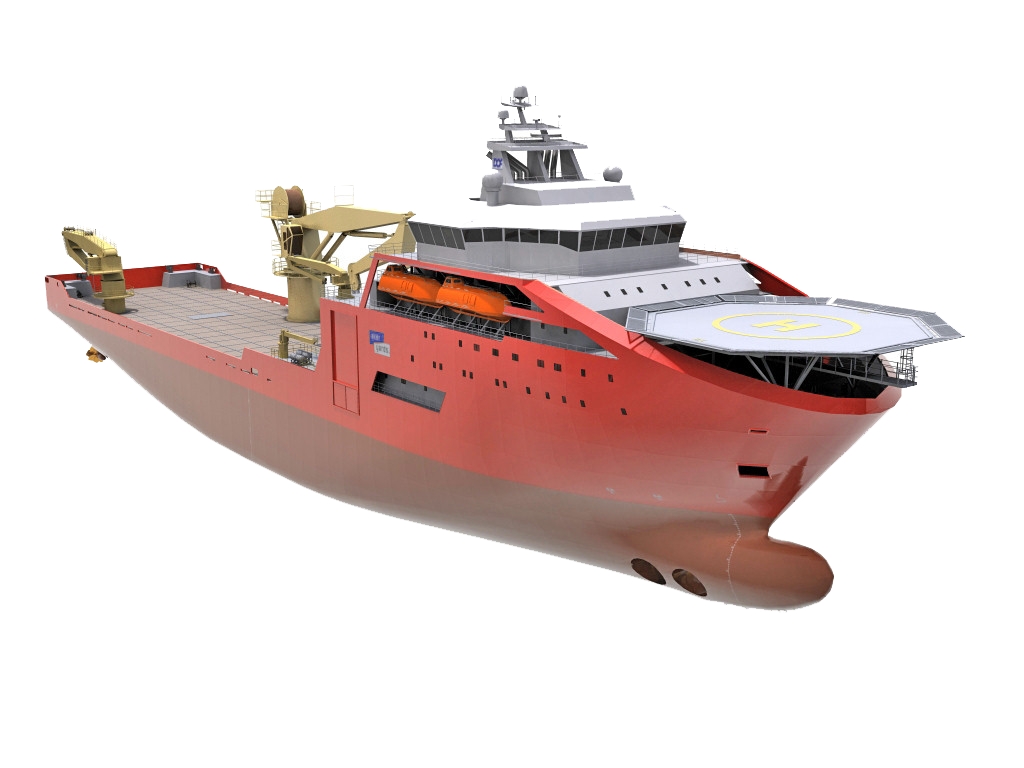
  • Offshore Drilling Platforms, Semi Submersibles, FPSOs
  • High Speed Craft - Hovercraft, Multi-Hull Ships, Hydrofoil Craft, etc
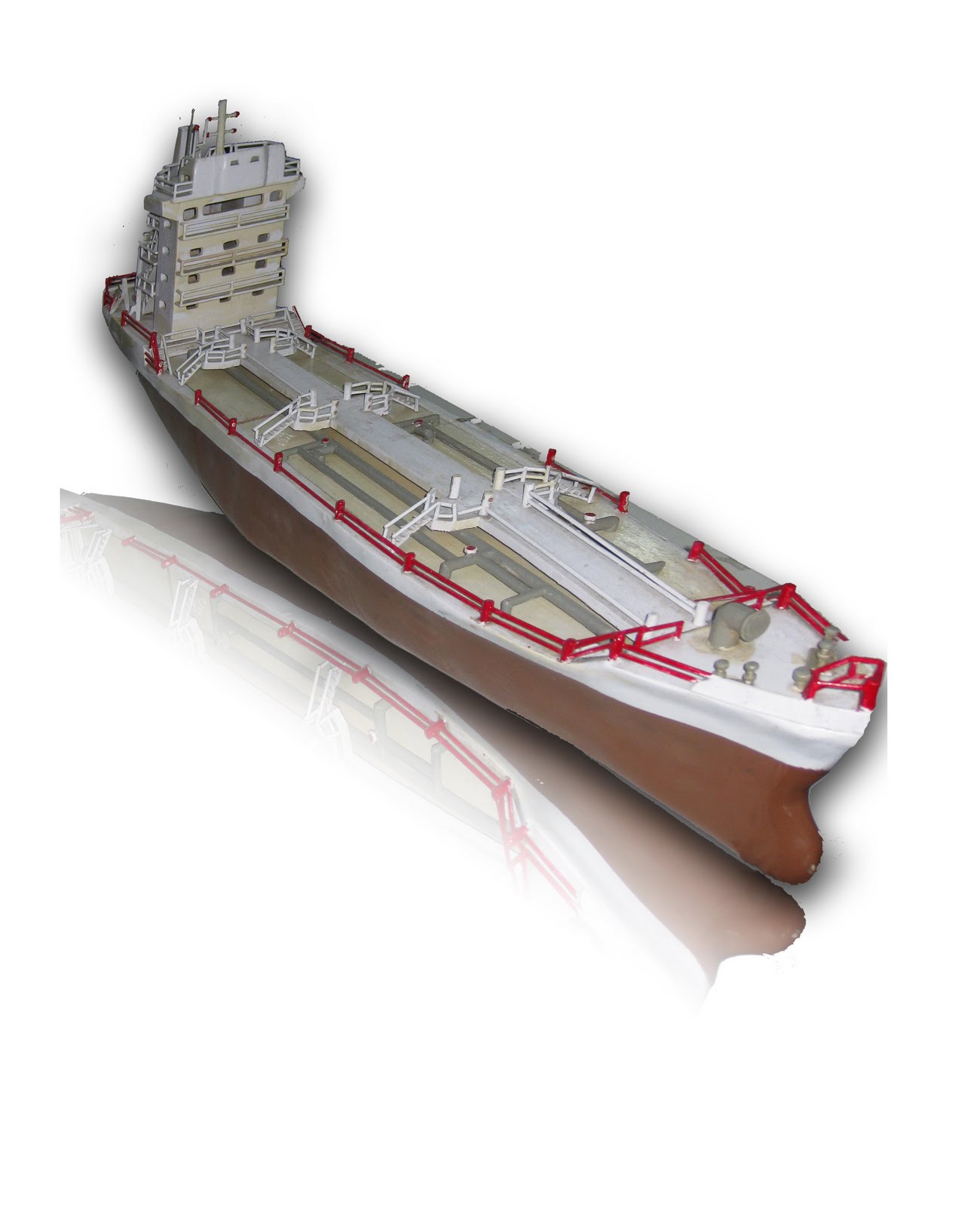
  • Workboats - Fishing Vessels, Tugs, Pilot Vessels, Rescue Craft etc
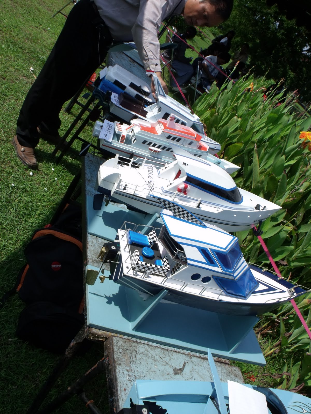
  • Yachts, Power Boats and other recreational craft

Some of these are among the largest and most complex and highly valued moveable structures produced by mankind. Without them to provide for the safe and efficient transport and recovery of the world's raw materials and products, modern society as we know it could not exist.

Modern engineering on this scale is essentially a team activity conducted by professional engineers in their respective fields and disciplines. However, it is the Naval Architect who integrates their activities and takes ultimate responsibility for the overall project. This demanding leadership role requires managerial qualities and ability to bring together the often conflicting demands of the various professional engineering disciplines involved to produce a product which is "fit for the purpose".

IntroductionIn addition to this vital managerial role, the Naval Architect has also a specialist function in ensuring that a safe, economic and seaworthy design is produced.

To undertake all these tasks the Naval Architect must have an understanding of many branches of engineering and must be in the forefront of high technology areas such as computer aided design and calculation. He or she must be able to utilise effectively the services provided by scientists, lawyers, accountants and business people of many kinds.

A Naval Architect requires a creative, enquiring and logical mind; the ability to communicate clearly in speech and writing with others inside and outside the engineering profession; sound judgment and qualities of leadership. The education and training given to the Naval Architect are designed to develop these skills and to lead him or her to recognised qualifications and professional status.

2. A Variety of Careers

Naval Architects have a wide range of employment opportunities, both in the UK and world-wide. They are involved in such a wide variety of work that it is difficult to categorise it comprehensively. However, the main areas are as follows:

  • A Variety of CareersDesign
  • Construction and Repair
  • Consultancy
  • Marketing and Sales
  • Operations
  • Regulation, Surveying and Overseeing
  • Research and Development
  • Education and Training

Each type of work has its own distinctive character and offers opportunities for initiative and imagination in a wide variety of technical and managerial posts as well as opportunities for foreign travel. The work place may be a large company, a small group, a consultancy or a government department.

Depending mainly on the type of qualifications held and personal inclination, Naval Architects may become specialists in one field or develop broad experience in several. Eventually they may find themselves in senior executive positions using their knowledge and experience of general management as well as their professional skills in engineering and project leadership. Indeed, aided by the breadth of their education, training and experience, professional Naval Architects are successful in top management posts in government, industry and commerce quite outside the maritime field.

Design

A Variety of Careers
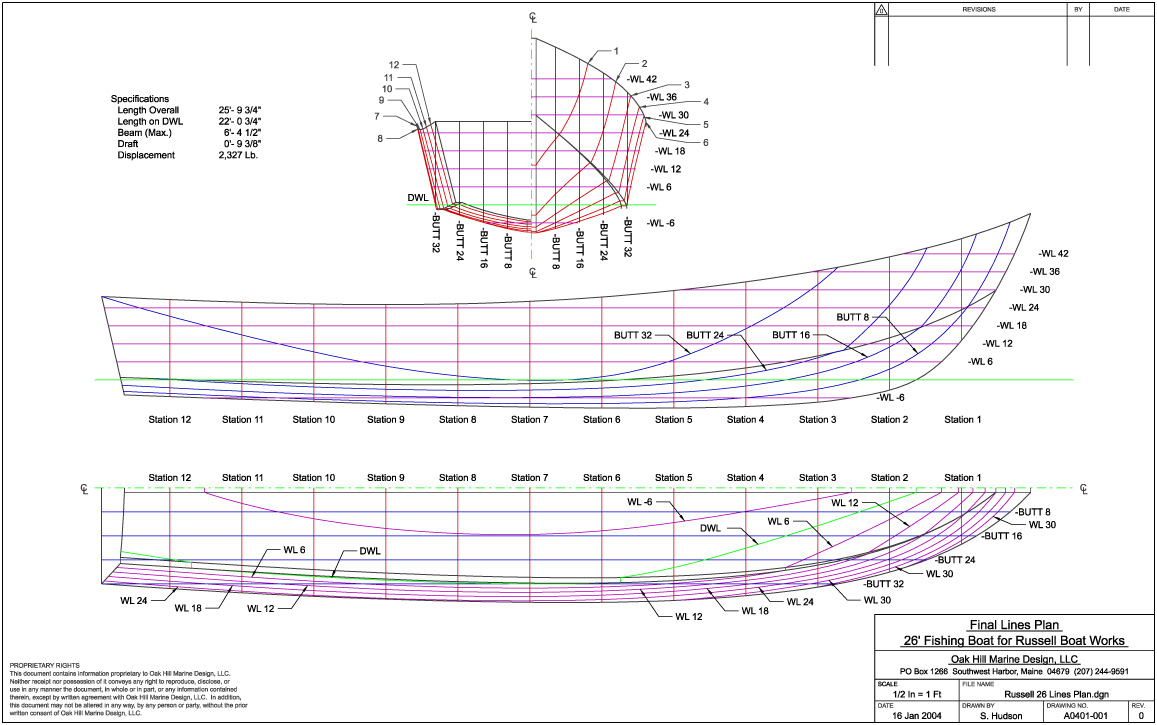
Naval Architects are by necessity creative people. They must have an understanding of the many facets of ship design - function, appearance and especially important at sea, safety. They must be team leaders, able to integrate the inputs of many others to achieve a balanced and coherent whole. Apart from the architectural aspects of ship form and layout, they must be able to use complex mathematical and physical models to ensure that the design is satisfactory technically and that it meets the safety rules and standards laid down by Classification Societies and Government Agencies.

A ship, boat or offshore structure must be stable, seaworthy and have adequate strength in all weathers as well as the hydrodynamic (and, for sailing craft, aerodynamic) performance to give economic propulsion and safe and comfortable motion in all sea states. The design process demands the extensive employment of computer based information and communication systems.

Employers of Naval Architects involved in design work include ship and boat builders, offshore constructors, design consultants, and for the ships and submarines of the Royal Navy, the Ministry of Defence. Major equipment manufacturers also employ teams of engineers, including Naval Architects, on the design of such products as propulsion systems, auxiliary systems, subsea production systems and control systems.

Construction and Repair

A Variety of CareersThe task of the ship and boat builder and offshore constructor is to convert drawings and detailed specifications into real structures. A Naval Architect specialising in construction usually holds a management post, taking responsibility for the management of the whole yard or for sections of it such as planning, production or the complex operation of fitting out. There is a continuous striving to make savings with existing techniques and equipment through the adoption of new processes and practices and by better training for the work force. The Naval Architect must also organise the supply of materials and components, inspection and testing as well as the vital resources of manpower.

Repair work has much in common with construction. Naval Architects in this field become professional managers who, like the builders, need to master modern management and associated techniques. Emergency repair work often offers opportunities for ingenuity and on-the-spot improvisation, and in the offshore engineering world in particular repair frequently involves underwater technology.

Employers of Naval Architects in construction and repair include both large and small shipbuilders and repairers, and those involved in the maintenance and repair of naval ships and submarines. A large proportion of senior technical managers and executives in the UK maritime industry are those who have been educated and trained as Naval Architects.

Consultancy

As consultants, Naval Architects provide clients with engineering solutions, technical and commercial guidance, support and project management for concept design studies, new vessel constructions, refits and conversions. The variety of work provides a rewarding challenge to the Naval Architect.

Marketing and Sales

Naval Architects are employed to give professional advice and technical support to customers of the maritime industry.

Operations

Many shipping companies have technical departments in which Naval Architects are responsible for the many phases of ship and equipment procurement and for solving problems affecting the economics of maritime operations.

Regulation, Surveying and Overseeing

Naval Architects employed by Classification Societies as Ship Surveyors are engaged world-wide in evaluating the safety of ships and marine structures using the Society's Rules and those of intergovernmental organisations such as the International Maritime Organisation. Plans of ships to be built and eventually classed with the Society are scrutinised, and aspects of design such as strength, stability, and lifesaving approved before construction.

During construction, Ship Surveyors carry out inspections to ensure that the quality of the workmanship and materials used is in accordance with the Rules and Regulations. Once the vessel or structure is in service, Ship Surveyors will continue to carry out inspections to ensure that any serious defects arising from operation are made good and that a safe and seaworthy structure is maintained. Government Departments employ Naval Architects who deal mainly with the framing of safety regulations and the surveying of ships and equipment from the safety point of view.

Ship operators and the Ministry of Defence employ Naval Architects to oversee the construction and repair of their vessels.

A Variety of CareersResearch and Development

Maritime research in the UK enjoys a high reputation world-wide and Naval Architects, many with post-graduate qualifications, are engaged in research in universities and industry throughout the country. Classification Societies also devote resources to Research and Development employing Naval Architects in this field.

Education and Training

Careers in engineering demand a sound education. Consequently, there is a need to attract Naval Architects with above average qualifications into Universities and Colleges as professors and lecturers.

3. How to Become a Naval Architect

A fully qualified Naval Architect is a member of The Royal Institution of Naval Architects (RINA) who is registered with the UK Engineering Council (EC) as a Chartered Engineer (CEng), Incorporated Engineer (IEng) or Engineering Technician (EngTech).

  • How to Become a Naval ArchitectChartered Engineers are primarily concerned with innovation, creativity and change, the development and use of new technologies, the promotion and use of advanced design and production methods, and the pioneering of new engineering services and management techniques in the field of naval architecture and maritime technology.
  • Incorporated Engineers are primarily concerned with the efficient management of existing technology at peak efficiency in the fields of naval architecture and maritime technology, and have managerial responsibility as leaders of teams, or individual responsibility at a high level.
  • Engineering Technicians are primarily concerned with the application of proven techniques to the solution of practical problems in the fields of naval architecture and maritime technology.

The RINA exercises strict controls over engineering professional standards for Naval Architects, and for membership it is necessary

  • to have an accredited academic qualification such as a degree or diploma, or to have passed examinations of an equivalent standard
  • to have received at least two years of training or a sufficient period of experience in lieu of training
  • to have held a relevant responsible position for at least two years
  • to have an aggregate of seven years of education, training and responsible experience after reaching the age of 18 years

The CEng, IEng and EngTech titles can only be obtained through membership of a professional engineering institution such as the RINA. There are classes of membership of the RINA which correspond to these titles. Members of the RINA are qualified to register as CEng, Associate Members as IEng and Associates as EngTech. Students who are studying to achieve the academic qualification required to become a Member, Associate Member or Associate may join the RINA as a Student Member. Those who have gained the academic qualification may then transfer to Graduate Member.

Such is the complexity of most engineering products that many people need to contribute as a team to the manufacturing process, whether as Chartered Engineers, Incorporated Engineers or Engineering Technicians, bringing together their different skills. This booklet is mainly intended for prospective Chartered Engineers and Incorporated Engineers, who require a degree as the educational qualification. However, the RINA can offer advice to those who are more interested in the practical aspects of naval architecture and who wish to become Engineering Technicians.

How to Become a Naval ArchitectEducation

The accreditation of a course by the RINA or another engineering professional institution ensures that its qualities are such that those who satisfy its requirements meet the educational standards of membership and registration. All accredited courses must contain certain features and essential components, but individual courses will differ in structure and content. The prospectuses of universities and colleges should be consulted in the initial selection of a course.

While the majority of Student Members will follow educational courses accredited by the RINA, students of other engineering disciplines who intend to work in the maritime industries are also eligible for membership. They should ensure that their studies will lead to an educational qualification which entitles them to become members of the RINA and register with the EC.

At school or college a broad range of subjects should be studied at GCSE level, covering both the arts and sciences, including the essential subjects Mathematics, Physics and English. These studies should lead to qualifications satisfying the entry requirements for either an accredited masters degree (MEng) course if proposing to become a Chartered Engineer, or a degree (BEng) course if intending to become an Incorporated Engineer. However, honours degree BEng graduates may also qualify for registration as a Chartered Engineer after completing additional academic studies, which may be achieved by a formal course at university or college, by distance learning such as through the Open University, by work based learning assessed during employment, or by a combination of these. Similarly, a diploma graduate may follow a similar route to qualify for registration as an Incorporated Engineer.

Applicants for entry to degree courses are normally expected to offer three GCE 'A' levels, or five Scottish 'Highers', with good grades in Mathematics and Physics. Acceptance on a particular course may be dependent on an interview as well as the grades achieved.

How to Become a Naval ArchitectBridges between educational routes exist, and students with suitable diploma qualifications may enter or transfer to BEng courses. Similarly, students may transfer from BEng to MEng courses.

All degree courses accredited by the RINA involve the study of engineering, materials, design theories and methods, mathematics and numerical methods, management, manufacturing systems and methods as well as naval architecture. At least 50% of each course marine orientated and contains a major project and engineering applications.

For those who are unable to attend a degree course, the RINA's educational requirements will be satisfied by passing the EC's examinations or an approved study profile for an Open University degree.

Candidates for membership of the RINA offering degrees accredited by other professional engineering institutions may be required to gain additional training/experience to compensate for any deficiencies in the above studies. Specialisation is a normal feature of a degree course and the options available may have a considerable influence on the choice of course.

A number of organisations including the RINA offer scholarships which provide additional financial support during an educational course.

Training

Although a number of companies have training schemes accredited by the RINA, the majority of trainees will need to work to individual programmes also approved by the RINA. In the latter case, the RINA can assist trainees in developing their individual training programmes.

When the company or individual training programme has been agreed, a senior engineer will be appointed to act as a mentor.

The Institution's training requirements call for a structured, broad and integrated programme, which should encompass the full range of practices applicable to the maritime industry. There are three parts to the Naval Architect's training:

How to Become a Naval ArchitectDesign

The trainee Naval Architect is required to gain an insight into the design process as well as communication and information systems by being involved in typical design issues such as requirements, functions, analyses, materials, production processes, quality, reliability, appearance and costs, hazard identification and risk assessment techniques.

Engineering Practice

Projects and departmental attachments are used to cover important applications to engineering and technology involving the wide range of materials and components employed in the marine industry, processes such as material forming, removal, joining and fabrication and their control, and assembly, installation and commissioning.


Management Services

The object of this part of training is to give the Naval Architect an awareness of important management practices such as production planning and control, quality control and assurance, interpersonal skills and personnel management, and commercial, marketing, legal and financial implications.

Some companies may not be able to provide all of the above required training themselves and may wish to attach their trainees to other organisations for certain parts of the planned training. Such attachments may also be used to cover vital elements more efficiently or to provide a broader appreciation of the wide range of expertise required by the Naval Architect.

When writing to potential sponsors or employers or responding to offers of training or sponsorship, it is important to enquire whether the company scheme meets, or the company is prepared to assist in meeting, the requirements of the RINA.

Experience

How to Become a Naval ArchitectAfter the completion of education and training there follows a period in which the prospective Naval Architects gain responsible experience in posts which require them to develop and prove fully their technical competence, and to demonstrate a satisfactory range of functions and characteristics such as the exercise of independent technical judgement requiring both practical experience and the application of engineering principles.

A minimum of two years of responsible experience is required and on completion an application should be made to the RINA for transfer to the class of Member or Associate Member, which authorises the use of the letters MRINA or AMRINA after a member's name. Successful candidates for transfer to Member or Associate Member will be offered registration with the EC which authorises them to also use the style or title of Chartered Engineer or Incorporated Engineer and the designatory letters CEng or IEng. Application may also be made by Chartered Engineers to the RINA to use the title of European Engineer (Eur Ing).

Professional Development

As a Chartered Engineer or Incorporated Engineer gains experience, the choice of career widens and after a few years opportunities may occur in many of the areas mentioned earlier. Later a Naval Architect may move from technical to general management to secure senior positions and ultimately directorships. While often regarded as being strictly vocational, engineering can also be an ideal base for a wide variety of careers outside the maritime industry.

Naval Architects must be prepared to keep abreast of developments in modern technology, to adapt to rapidly changing circumstances and to take advantage of new career opportunities as they arise. Continuing professional development (CPD) is therefore essential and can be achieved through courses and conferences which are organised by the RINA and other engineering professional institutions or organisations on new technologies, management systems, communication, business and many other topics. Naval Architects may also keep up-to-date by reading technical journals and papers published by professional institutions.

4. The Royal Institution of Naval Architects

The Royal Institution of Naval ArchitectsFounded in 1860, The Royal Institution of Naval Architects is an internationally renowned professional engineering institution whose members are involved at all levels in the design, construction, repair and operation of ships, boats and marine structures. Members of the RINA are widely represented in industry, universities and colleges, and maritime organisations worldwide. There are classes of membership to suit all those who are professionally qualified in naval architecture, or who are involved or interested in the maritime industry.

The RINA enjoys an outstanding reputation for the quality and range of its technical publications, covering all aspects of naval architecture and the maritime industry. The RINA also organises an extensive and successful programme of international conferences and training courses covering a broad range of experience and opinion on research, development and operation of all aspects of naval architecture.

Membership of the RINA gives the following benefits and services:

  • A professional qualification which is internationally recognised as demonstrating the achievement of the highest standards of professional competence
  • Free copies of the leading technical journals, The Naval Architect, Offshore Marine Technology and Warship Technology, and reduced rates on all other RINA publications
  • Reduced rates for all RINA international conferences and training courses
  • Advice and assistance on all aspects of academic study, training and professional development
  • Access to library and technical research facilities
  • Opportunity to meet and exchange views with other professionals in the maritime industry, at local Branch meetings and conferences

Students at schools and colleges who are studying to enter university and are interested in a career as a Naval Architect may also join the RINA as a Student Companion member. Further information can be obtained from the Professional Affairs Department.

5. Information


The Professional Affairs Department of the Royal Institution of Naval Architects can advise on suitable courses in naval architecture and related subjects. The Professional Affairs Departmentcan also advise students on any other engineering courses who may subsequently wish to consider a career in naval architecture

Rabu, 21 Juli 2010

oil platform

Oil platform

From Wikipedia, the free encyclopedia

Jump to: navigation, search
A typical offshore Oil/Gas platform.

An offshore platform, often referred to as an oil platform or an oil rig, is a lаrge structure used in offshore drilling to house workers and machinery needed to drill wells in the ocean bed, extract oil or natural gas, or both, process the produced fluids, and ship or pipe them to shore. Depending on the circumstances, the platform may be fixed to the ocean floor, may consist of an artificial island, or may float.[1]

Remote subsea wells may also be connected to a platform by flow lines and by umbilical connections; these subsea solutions may consist of single wells or of a manifold centre for multiple wells.

Contents

[hide]

[edit] History

Offshore platform Gulf of Mexico

Around 1891 the first submerged oil wells were drilled from platforms built on piles in the fresh waters of the Grand Lake St. Marys (a.k.a. Mercer County Reservoir) in Ohio. The wide but shallow reservoir was built from 1837 to 1845 to provide water to the Miami and Erie Canal.

Around 1896 the first submerged oil wells in salt water were drilled in the portion of the Summerland field extending under the Santa Barbara Channel in California. The wells were drilled from piers extending from land out into the channel.

Other notable early submerged drilling activities occurred on the Canadian side of Lake Erie in the 1900s and Caddo Lake in Louisiana in the 1910s. Shortly thereafter, wells were drilled in tidal zones along the Gulf Coast of Texas and Louisiana. The Goose Creek field near Baytown, Texas is one such example. In the 1920s drilling was done from concrete platforms in Lake Maracaibo, Venezuela.

The oldest subsea well recorded in Infield's offshore database is the Bibi Eibat well which came on stream in 1923 in Azerbaijan. Landfill was used to raise shallow portions of the Caspian Sea.

In the early 1930s the Texas Company developed the first mobile steel barges for drilling in the brackish coastal areas of the gulf.

In 1937 Pure Oil Company (now part of Chevron Corporation) and its partner Superior Oil Company (now part of ExxonMobil Corporation) used a fixed platform to develop a field in 14 feet of water, one mile offshore of Calcasieu Parish, Louisiana.

In 1946, Magnolia Petroleum Company (now part of ExxonMobil) erected a drilling platform in 18 ft of water, 18 miles[vague] off the coast of St. Mary Parish, Louisiana.

In early 1947 Superior Oil erected a drilling/production platform in 20 ft of water some 18 miles[vague] off Vermilion Parish, Louisiana. But it was Kerr-McGee Oil Industries (now Anadarko Petroleum Corporation), as operator for partners Phillips Petroleum (ConocoPhillips) and Stanolind Oil & Gas (BP), that completed its historic Ship Shoal Block 32 well in October 1947, months before Superior actually drilled a discovery from their Vermilion platform farther offshore. In any case, that made Kerr-McGee's well the first oil discovery drilled out of sight of land.[2][3]

The Thames Sea Forts of World War II are considered the direct predecessors of modern offshore platforms. Having been pre-constructed in a very short time, they were then floated to their location and placed on the shallow bottom of the Thames estuary.[4][5]

[edit] Types

Larger lake- and sea-based offshore platforms and drilling rigs are some of the largest moveable man-made structures in the world. There are several types of oil platforms and rigs:

1, 2) conventional fixed platforms; 3) compliant tower; 4, 5) vertically moored tension leg and mini-tension leg platform; 6) Spar ; 7,8) Semi-submersibles ; 9) Floating production, storage, and offloading facility; 10) sub-sea completion and tie-back to host facility.[6]

[edit] Fixed platforms

A fixed platform base under construction on a Louisiana river

These platforms are built on concrete or steel legs, or both, anchored directly onto the seabed, supporting a deck with space for drilling rigs, production facilities and crew quarters. Such platforms are, by virtue of their immobility, designed for very long term use (for instance the Hibernia platform). Various types of structure are used, steel jacket, concrete caisson, floating steel and even floating concrete. Steel jackets are vertical sections made of tubular steel members, and are usually piled into the seabed. Concrete caisson structures, pioneered by the Condeep concept, often have in-built oil storage in tanks below the sea surface and these tanks were often used as a flotation capability, allowing them to be built close to shore (Norwegian fjords and Scottish firths are popular because they are sheltered and deep enough) and then floated to their final position where they are sunk to the seabed. Fixed platforms are economically feasible for installation in water depths up to about 1,700 ft (520 m).

[edit] Compliant towers

These platforms consist of slender flexible towers and a pile foundation supporting a conventional deck for drilling and production operations. Compliant towers are designed to sustain significant lateral deflections and forces, and are typically used in water depths ranging from 1,500 to 3,000 feet (460 to 910 m).

[edit] Semi-submersible platform

Platform P-51 off the Brazilian coast is a semi-submersible platform

These platforms have hulls (columns and pontoons) of sufficient buoyancy to cause the structure to float, but of weight sufficient to keep the structure upright. Semi-submersible platforms can be moved from place to place; can be ballasted up or down by altering the amount of flooding in buoyancy tanks; they are generally anchored by combinations of chain, wire rope or polyester rope, or both, during drilling or production operations, or both, though they can also be kept in place by the use of dynamic positioning. Semi-submersibles can be used in water depths from 200 to 10,000 feet (60 to 3,000 m).

[edit] Jack-up platforms

Jack-up platforms (or jack-ups), as the name suggests, are platforms that can be jacked up above the sea using legs that can be lowered, much like jacks. These platforms are typically used in water depths up to 400 feet (120 m), although some designs can go to 550 ft (170 m) depth. They are designed to move from place to place, and then anchor themselves by deploying the legs to the ocean bottom using a rack and pinion gear system on each leg.

[edit] Drillships

A drillship is a maritime vessel that has been fitted with drilling apparatus. It is most often used for exploratory drilling of new oil or gas wells in deep water but can also be used for scientific drilling. Early versions were built on a modified tanker hull, but purpose-built designs are used today. Most drillships are outfitted with a dynamic positioning system to maintain position over the well. They can drill in water depths up to 12,000 ft (3,700 m)[7].

[edit] Floating production systems

The main types of floating production systems are FPSO (floating production, storage, and offloading system). FPSOs consist of large monohull structures, generally (but not always) shipshaped, equipped with processing facilities. These platforms are moored to a location for extended periods, and do not actually drill for oil or gas. Some variants of these applications, called FSO (floating storage and offloading system) or FSU (floating storage unit), are used exclusively for storage purposes, and host very little process equipment.

[edit] Tension-leg platform

TLPs are floating platforms tethered to the seabed in a manner that eliminates most vertical movement of the structure. TLPs are used in water depths up to about 6,000 feet (2,000 m). The "conventional" TLP is a 4-column design which looks similar to a semisubmersible. Proprietary versions include the Seastar and MOSES mini TLPs; they are relatively low cost, used in water depths between 600 and 4,300 feet (180 and 1,300 m). Mini TLPs can also be used as utility, satellite or early production platforms for larger deepwater discoveries.

A 'Statfjord' Gravity base structure under construction in Norway. Almost all of the structure will end up submerged.

[edit] Spar platforms

Spars are moored to the seabed like TLPs, but whereas a TLP has vertical tension tethers, a spar has more conventional mooring lines. Spars have to-date been designed in three configurations: the "conventional" one-piece cylindrical hull, the "truss spar" where the midsection is composed of truss elements connecting the upper buoyant hull (called a hard tank) with the bottom soft tank containing permanent ballast, and the "cell spar" which is built from multiple vertical cylinders. The spar has more inherent stability than a TLP since it has a large counterweight at the bottom and does not depend on the mooring to hold it upright. It also has the ability, by adjusting the mooring line tensions (using chain-jacks attached to the mooring lines), to move horizontally and to position itself over wells at some distance from the main platform location. The first production spar was Kerr-McGee's Neptune, anchored in 1,930 ft (590 m) in the Gulf of Mexico; however, spars (such as Brent Spar) were previously used as FSOs.

Eni's Devil's Tower located in 5,610 ft (1,710 m) of water, in the Gulf of Mexico, was the world's deepest spar until 2010. The world's deepest platform is currently the Perdido spar in the Gulf of Mexico, floating in 2,438 meters of water. It is operated by Royal Dutch Shell and was built at a cost of $3 billion.[8]

The first Truss spars were Kerr-McGee's Boomvang and Nansen. The first (and only) cell spar is Kerr-McGee's Red Hawk[9].

[edit] Normally unmanned installations (NUI)

These installations (sometimes called toadstools) are small platforms, consisting of little more than a well bay, helipad and emergency shelter. They are designed to operate remotely under normal conditions, only to be visited occasionally for routine maintenance or well work.

[edit] Conductor support systems

These installations, also known as satellite platforms, are small unmanned platforms consisting of little more than a well bay and a small process plant. They are designed to operate in conjunction with a static production platform which is connected to the platform by flow lines or by umbilical cable, or both.

[edit] Particularly large examples

The Petronius Platform is a compliant tower in the Gulf of Mexico, which stands 2,000 feet (610 m) above the ocean floor. It is one of the world's tallest structures.[10]

The Hibernia platform is the world's largest (in terms of weight) offshore platform, located on the Jeanne D'Arc basin, in the Atlantic Ocean off the coast of Newfoundland. This Gravity base Structure (GBS), which sits on the ocean floor, is 364 feet (111 m) high and has storage capacity for 1.3 million barrels (210,000 m3) of crude oil in its 278.8-foot (85.0 m) high caisson. The platform acts as a small concrete island with serrated outer edges designed to withstand the impact of an iceberg. The GBS contains production storage tanks and the remainder of the void space is filled with ballast with the entire structure weighing in at 1.2 million tons.

[edit] Maintenance and supply

A typical oil production platform is self-sufficient in energy and water needs, housing electrical generation, water desalinators and all of the equipment necessary to process oil and gas such that it can be either delivered directly onshore by pipeline or to a floating platform or tanker loading facility, or both. Elements in the oil/gas production process include wellhead, production manifold, production separator, glycol process to dry gas, gas compressors, water injection pumps, oil/gas export metering and main oil line pumps.

Larger platforms are assisted by smaller ESVs (emergency support vessels) like the British Iolair that are summoned when something has gone wrong, e.g. when a search and rescue operation is required. During normal operations, PSVs (platform supply vessels) keep the platforms provisioned and supplied, and AHTS vessels can also supply them, as well as tow them to location and serve as standby rescue and firefighting vessels.

[edit] Crew

[edit] Essential personnel

Not all of the following personnel are present on every platform. On smaller platforms, one worker can perform a number of different jobs. The following also are not names officially recognized in the industry:

  • OIM (offshore installation manager) who is the ultimate authority during his/her shift and makes the essential decisions regarding the operation of the platform;
  • operations team leader (OTL);
  • offshore operations engineer (OOE) who is the senior technical authority on the platform;
  • PSTL or operations coordinator for managing crew changes;
  • dynamic positioning operator, navigation, ship or vessel maneuvering (MODU), station keeping, fire and gas systems operations in the event of incident;
  • second mate to meet manning requirements of flag state, operates fast rescue craft, cargo operations, fire team leader;
  • third mate to meet manning requirements of flag state, operate fast rescue craft, cargo operations, fire team leader;
  • ballast control operator to operate fire and gas systems;
  • crane operators to operate the cranes for lifting cargo around the platform and between boats;
  • scaffolders to rig up scaffolding for when it is required for workers to work at height;
  • coxswains to maintain the lifeboats and manning them if necessary;
  • control room operators, especially FPSO or production platforms;
  • catering crew, including people tasked with performing essential functions such as cooking, laundry and cleaning the accommodation;
  • production techs to run the production plant;
  • helicopter pilot(s) living on some platforms that have a helicopter based offshore and transporting workers to other platforms or to shore on crew changes;
  • maintenance technicians (instrument, electrical or mechanical).

[edit] Incidental personnel

Drill crew will be on board if the installation is performing drilling operations. A drill crew will normally comprise:

Well services crew will be on board for well work. The crew will normally comprise:

  • Well services supervisor
  • Wireline or coiled tubing operators
  • Pump operator

[edit] Drawbacks

[edit] Risks

The nature of their operation — extraction of volatile substances sometimes under extreme pressure in a hostile environment — means risk; accidents and tragedies occur regularly. The U.S. Minerals Management Service reported 69 offshore deaths, 1,349 injuries, and 858 fires and explosions on offshore rigs in the Gulf of Mexico from 2001 to 2010.[11] In July 1988, 167 people died when Occidental Petroleum's Piper Alpha offshore production platform, on the Piper field in the UK sector of the North Sea, exploded after a gas leak. The resulting investigation conducted by Lord Cullen and publicized in the first Cullen Report was highly critical of a number of areas, including, but not limited to, management within the company, the design of the structure, and the Permit to Work System. The report was commissioned in 1988, and was delivered November 1990.[12] The accident greatly accelerated the practice of providing living accommodations on separate platforms, away from those used for extraction.

However, this was in itself a hazardous environment. In March 1980, the 'flotel' (floating hotel) platform Alexander L. Kielland capsized in a storm in the North Sea with the loss of 123 lives.[13]

In 2001, Petrobras 36 in Brazil exploded and sank five days later, killing 11 people.

Given the number of grievances and conspiracy theories that involve the oil business, and the importance of gas/oil platforms to the economy, platforms in the United States are believed to be potential terrorist targets. Agencies and military units responsible for maritime counterterrorism in the US (Coast Guard, Navy SEALs, Marine Recon) often train for platform raids.

On April 20, 2010, the Deepwater Horizon platform, 52 miles off-shore of New Orleans, (property of Transocean and leased to BP) exploded, killing 11 people, and sank two days later. The resulting undersea gusher, conservatively estimated to exceed 20 million gallons as of early June, 2010, became the worst oil spill in US history, eclipsing the Exxon Valdez oil spill.

[edit] Ecological effects

NOAA map of the 3,858 oil and gas platforms extant in the Gulf of Mexico in 2006

In British waters, the cost of removing all platform rig structures entirely was estimated in 1995 at £1.5 billion, and the cost of removing all structures including pipelines—called a "clean sea" approach—at £3 billion.[citation needed]

In the United States, Marine Biologist Milton Love has proposed that oil platforms off the California coast be retained as artificial reefs, instead of being dismantled (at great cost), because he has found them to be havens for many of the species of fish which are otherwise declining in the region, in the course of 11 years of research.[14] Love is funded mainly by government agencies, but also in small part by the California Artificial Reef Enhancement Program. NOAA has said it is considering this course of action, but wants money to study the effects of the rigs in detail. Divers have been used to assess the fish populations surrounding the platforms.[15] In the Gulf of Mexico, more than 200 platforms have been similarly converted.[citation needed]

[edit] Deepest oil platforms

The world's deepest oil platform is the floating Independence Hub which is a semi-submersible platform in the Gulf of Mexico in a water depth of 2,414 metres (7,920 ft).

Non-floating compliant towers and fixed platforms:

[edit] See also

[edit] References

  1. ^ Oil Rigs and Platforms
  2. ^ Ref accessed 02-12-89 by technical aspects and coast mapping. Kerr-McGee
  3. ^ Project Redsand
  4. ^ Project Redsand
  5. ^ 11.2 Azerbaijan's Oil History Brief Oil Chronology since 1920 ­ Part 2 by Mir-Yusif Mir-Babayev
  6. ^ Office of Ocean Exploration and Research (15 December 2008). "Types of Offshore Oil and Gas Structures". NOAA Ocean Explorer: Expedition to the Deep Slope. National Oceanic and Atmospheric Administration. http://oceanexplorer.noaa.gov/explorations/06mexico/background/oil/media/types_600.html. Retrieved 23 May 2010.
  7. ^ "Chevron Drillship accessdate=2010-05-24". 2010-03-11. http://www.chevron.com/news/press/release/?id=2010-03-11.
  8. ^ Shell starts production at Perdido
  9. ^ "First Cell Spar accessdate=2010-05-24". http://www.fmctechnologies.com/en/SubseaSystems/GlobalProjects/NorthAmerica/US/KMGRedHawk.aspx?tab=%7BB01D40AB-5E2F-4710-9543-19C658AF29F5%7D.
  10. ^ "What is the World's Tallest Building?". All About Skyscrapers. 2009. http://www.allaboutskyscrapers.com/tallest_building.htm. Retrieved 23 May 2010.
  11. ^ "Potential for big spill after oil rig sinks". MSNBC. 2010-04-22. http://www.msnbc.msn.com/id/36683314/ns/us_news-life/. Retrieved 2010-06-04.
  12. ^ http://www.oilandgas.org.uk/issues/piperalpha/v0000864.cfm
  13. ^ "North Sea platform collapses". BBC News. 1980-03-27. http://news.bbc.co.uk/onthisday/hi/dates/stories/march/27/newsid_2531000/2531091.stm. Retrieved 2008-06-19.
  14. ^ Page M, Dugan J, Love M, Lenihan H.. "Ecological Performance and Trophic Links: Comparisons Among Platforms And Natural Reefs For Selected Fish And Their Prey". http://www.coastalresearchcenter.ucsb.edu/cmi/ecoperformance.html. Retrieved 2008-06-27.
  15. ^ SA Cox, CR Beaver, QR Dokken, and JR Rooker. (1996). "Diver-based under water survey techniques used to assess fish populations and fouling community development on offshore oil and gas platform structures.". In: MA Lang, CC Baldwin (Eds.) The Diving for Science…1996, "Methods and Techniques of Underwater Research". Proceedings of the American Academy of Underwater Sciences (16th Annual Scientific Diving Symposium). http://archive.rubicon-foundation.org/4689. Retrieved 2008-06-27.

[edit] External links

Label